
3384 阅读 2020-02-07 18:44:04 上传
Surround-Screen Mobile based Projection: Design and Implementation
of Mobile Cave Virtual Reality
Abdel Ghani Karkar, Member, IEEE, Muhammad E. H. Chowdhury, Member, IEEE, and Naveed Nawaz
Abstract—Virtual Reality (VR) is the employment of computer devices to simulate real or imaginary environments. Conventional user interfaces stresses the usage of screen displays to interact with the developed environment. The prospect of VR enables the user to be virtually inside the environment. CAVE is one kind of room-shaped VR technology that displays the environment on its walls. We observe some common limitations in the existing CAVE technology, such as fixed space requirements and the difficulty in moving it. In the current work, we present a novel mobile-CAVE system that uses light-weighted materials and portable powered devices. It solves the limitation of re-using the allocated space by packing it and the ability to move it easily. We have assessed our technology by performing usability analysis, power consumption, and mobility experimental study. The profound experiments demonstrated the efficiency of the proposed technology in comparison with former CAVE system.
Index Terms—Virtual Reality, CAVE, Sustainable Development, Projection Paradigms, Mobile technology
1 INTRODUCTION
CAVE is an acronym of cave automatic virtual reality (VR). It is an immersive technology that uses a number of pointing projectors [1] or flat displays positioned [2] between three to six cubical room-sized space. The CAVE was invented by Cruz-Neira et al. [1] in 1992. The wall graphical presentation must be with high-resolution due to the close viewing range which needs small pixels to possess the imagination of reality. Diverse technologies have been proposed to promote CAVE [3], [4]. However, some popular limitations in existing CAVE systems have not been addressed yet:
1) Space Allocation: CAVE requires adequate space for its materials. The space allocation of CAVE varies according to its model. Allocated space might be permanent.
2) Mobility: The setup of the CAVE in particular space is considered nearly constant. It is not easy to move the CAVE setup to another area.
3) Power Consumption: In order to operate the CAVE, required devices and computers with associated projectors must be switched on. However, the environmental and power consumption metrics are not considered.
4) Cost: The cost of the CAVE is high, including high-end devices, projectors, walls-sized displays, and the cubical metal room.
On the research aspect, diverse CAVE applications have been recently published such as virtual experience for thematic tourism [5] and vConnect Cave system [6]. Encouraged by the above proposed systems, we investigate that a CAVE system that overcomes current limitations. Although, available CAVE applications can be adopted and used in our proposed solution.
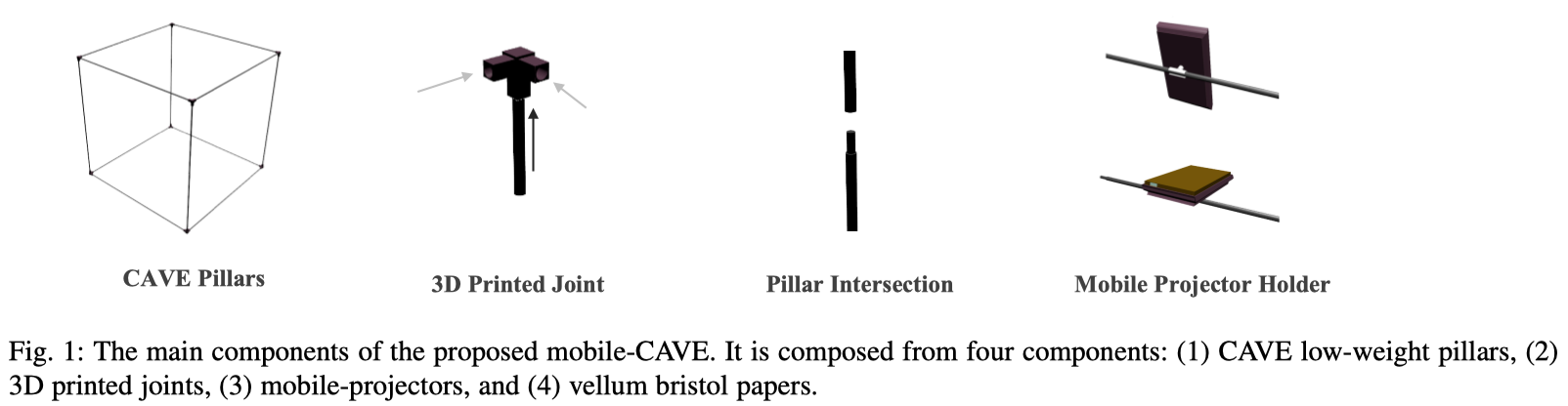
In the current work, we present a novel mobile-CAVE system. It solves the limitation of space allocation by merely packing CAVE equipments. It overcomes the mobility limitation by using light-weighted materials. It reduces significantly the power consumption through the employment of mobile based devices such as mobile projectors, laptops and mobile devices. Additionally, it decreases the cost of former CAVE technology as well as the maintenance of corrupted materials. As shown in Figure 1, the design is composed from: (1) mobile-projectors, (2) 3D printed joints, (3) CAVE low-weight pillars, and (4) vellum bristol paper.
We have compared the usability and the power consumption of our proposed mobile-CAVE with the former CAVE [1] supplied with three walls and one ground projection. Moreover, we have asked our participants to try moving the mobile-CAVE to make the setup in a new place. And also, we asked them to fill a survey to show their satisfaction. The rest of the paper is organized as follows: in section 2, we discuss the historical literature of the CAVE. In section 3, we provide details about our proposed solution. In section 4, we present and discuss experiments and user studies. And finally, in section 5, we conclude the paper.
2 LITERATURE R EVIEW
The CAVE was invented by a team of researchers at Electronic Visualization Lab at University of Illinois’ [7]. It was created for a challenge of making one-to-many visualization instrument that uses large projection screens. The CAVE is generally 10 x 10 x 10 inches cubical room placed in darkened room [1]. Modern CAVE systems can project walls using reflected mirrors placed and adjusted between high-resolution projectors. The projection requires specific setup to ensure more immersive environment to avoid edges between walls [1], [8].
Input and output devices such as tactile devices, haptic, or surrounded 3D sound have been used in the CAVE such as Wireless Ergonomic Lightweight Device (WiELD-CAVE) [4]. Gloves also have been used to provide the ability of using hand fingers [9]. Cabral et al. [10] examined a two-dimentional gesture identification system that can be used in virtual reality environment, such as the CAVE. The system does not require a participant to wear gloves in order to interact with the virtual environment. Nan et al. [11] designed a hand-enabled interaction application for CAVE, called vDesign. The application enables the user to use his hand in order to interact with objects in the virtual environment. The experimental analysis of the proposed application showed accurate results in contrast with traditional wand CAVE interactions. The CAVE is used vastly in scientific research and data visualization. For instance, Leah et al. [12] proposed an immersive virtual reality framework for instructional materials to efficiently combine the technology and make change for practical learning. And, Kageyama et al. [3] developed a framework for scientific visualization called Multiverse. It can operate in CAVE virtual reality environment and invoke visualization programs. In addition to that, the CAVE is used to simulate medical applications in order to analyze advanced studies for brain tumor surgeries [13]. The CAVE is used as well for entertainment [14], edutainment [15], and for diverse simulation purposes [16], [17].
In the other hand, researchers conducted studies to provide standardized application-programming interface (API) to support the development of virtual environment for CAVE, such as VR Juggler [18] and FreeVR [19]. Collaborative CAVE support was also also considered to enable multiple users work together [20].
Over the years, the CAVE is promoted by improving its quality and by providing different technological hardware features [3]. Improving the quality requires scientific studies along with experimental analysis that assesses its performance and its usability. Providing features requires feasibility study and market research in order to identify the requirements of clients, such as organizational or industrial needs 1 . Zhou et al. [21] proposed a maintenance space evaluation method examines ergonomic aspect. The maintenance space have been evaluated by comparing free and constraint virtual environment. The obtained result demonstrated the efficiency of the proposed method. The financial requirements to construct and setup a CAVE are considerably higher than normal desktop computers [22].
While diverse researches have been conducted, the limitations of CAVE virtual reality system are yet not solved. In this paper, we propose a novel mobile-CAVE system uses low-weighted materials. It solves the limitation of space allocation, mobility,and decreases the power-consumption. The profound experimental studies showed the effectiveness of our CAVE.

3 MOBILE C AVE D ESIGN
In this section, we present the prime components of our proposed CAVE system. First, we introduce the architectural design of the CAVE. Second, we present the technological hardware that are applicable. And third, we elaborate on the network communication layer between the devices, such as laptop or mobile smart devices.
3.1 Architectural Design
In order to build effortless mobile-CAVE, we designed its pillars with light-weighted metal poles, see Figure 1. These poles can be easily attached and detached from each other according to the desired size. The length of the three connected poles is three meters. The joints of pillars are 3D printed using AcrylonitrilleButadiene-styrene (ABS) polymers [23]. Screws are not required to make the setup. We designed holders to put mobile-based projectors on the top of the mobile-CAVE. Digital devices, such as laptops or smart phones, can be placed next to the mobile-CAVE. Figure 2 shows the architectural model of the mobile-CAVE.
3.2 Hardware Deployment and Connectivity
Our CAVE is designed to operate with mobile projectors. Thus, projectors according to their specifications can be connected with wires, such as high-definition multimedia interface (HDMI) [24], or wirelessly with WiFi connection. The communication between devices is central [25]. The main hosting device is responsible about establishing the connection. The hosting device can be also configured to connect external devices. This is useful to supply proposed system with collaborative mobile-CAVE virtual environments.
3.3 Projection Setup
The setup of projectors is done manually by rotating projectors in their holders. An optimal picture is obtained when all displays have wide view with no splitting corners. The projection on the wall depends on the mobile-projector model. Thus, the projection alignment [26], [27] may differ according to the projector model.
4 METHODS AND E XPERIMENTS
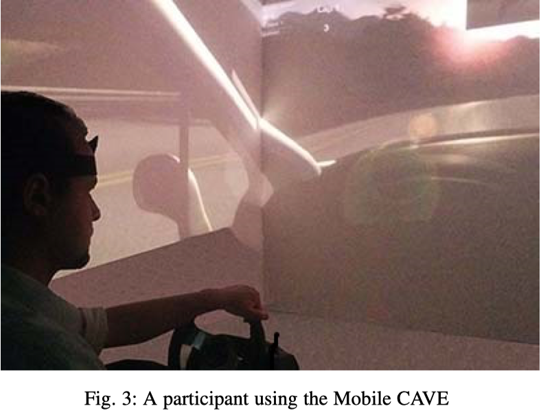
In order to quantitatively assess the different CAVE technologies, we developed a driving simulation game in Unity 3D [28]. The architecture of the game is client-server architecture. The server is the main machine that is responsible about building the virtual world, computing required paths, and synchronizing elements on connected clients. For the movement tracking, we employed existing marker tracking system in order to update the virtual environment. It uses infrared cameras to track attached light sources. For the 3D view, we employed anaglyphic view to simulate the 3D scenes. We run the simulation in standard CAVE and the proposed mobile-CAVE. We used different projection modes to assess the different qualities of the projection. Figure 3 shows a sample participant using the mobile-CAVE.
Heart Rate Variability (HRV) was used to gauge the physiological state of participants in the quantitative evaluation of the CAVE performance. To measure HRV, portable wireless B-Alert x10 (BIOPAC Systems, Inc.) Electrocardiogram (ECG) system was used with two Ag/AgCl electrodes attached to a participants chest. Following the recommendation of the supplier, the points of attachment were (i) under the right collarbone, and (ii) under lowest left rib bone of the participant. ECG signal was band passed through a filter (0.05-100 Hz) digitized at a sampling frequency of 1000 Hz with 12-bit resolution. Data were stored on the hard disk of an Intel Core i7 Personal Computer for off line analysis. ECG signal was recorded using the B-Alert Pro software accompanied with the B-Alert x10 system2 .
The engagement-HRV analysis for a given period was accomplished using Kubios HRV [29]. And the obtained sequence of beat-to-beat (RR) intervals were manually examined and edited for movement artifacts. For the time-domain analysis, the most evident time-domain measure is the mean value of RR intervals (RR) and corresponding mean Heart Rate (HR), which are applied straight to the series of successive RR interval values. The standard deviation of RR intervals (SDNN ) is defined as
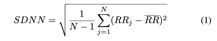
where RRj denotes the value of j th RR interval and N is the total number of successive intervals. The SDNN reflects the overall variation within the RR interval series.
In the frequency-domain analysis, a power spectrum density (PSD) estimate is calculated for the RR interval series. The regular PSD estimators implicitly assume equidistant sampling and, thus, the RR interval series is converted to equidistantly sampled time series sampled at four samples/sec by cubic spline interpolation methods prior to PSD estimation using Kubios HRV software.
In HRV analysis, the PSD estimation is generally carried out using either Fast Fourier Transform (FFT) based methods [30] or parametric autoregressive (AR) modeling based methods [31]. The advantage of FFT based methods is the simplicity of implementation, while the AR spectrum yields improved resolution especially for short samples. In this work, the HRV spectrum was calculated with the AR method (model order was 16) without spectrum factorization. The frequency-domain measures extracted from the PSD estimate for each frequency band include absolute and relative powers of VLF, LF, and HF bands, LF and HF band powers in normalized units, the LF/HF power ratio, and peak frequencies for each band. Absolute power values for each frequency band were obtained by simply integrating the spectrum over the band limits.
4.1 Projection Analysis
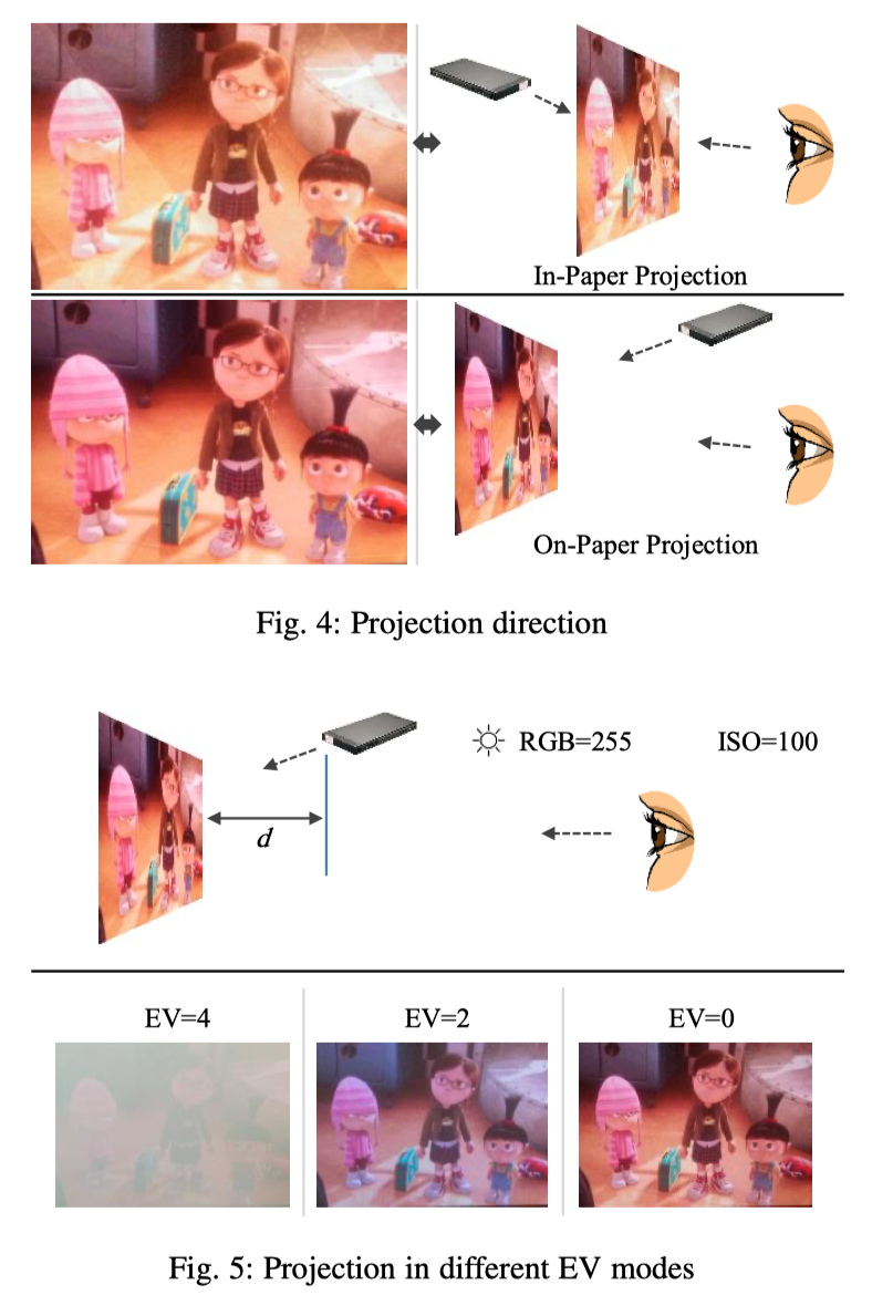
An experiment was carried out to compare the projection on the paper from outside and from inside of the CAVE as shown in Figure 4. Consequently, we analyzed the projection on the paper in different environments in order to select the optimal design of the mobile-CAVE. We compared the different lighting conditions and the obtained picture quality. The dimension of the projection was configured to 60 inch and the used distance between projector and screen was d=2 meters. In addition, we compared the obtained pictures with different exposure values (EV) at four (EV=4), two (EV=2), and zero (EV=0) respectively as shown in Figure 5.
The projection on the paper showed better picture quality than the projection through the paper. This is because the projection from inside results distortion caused by the fibers of the paper as shown in Figure 4. In Figure 5, the three different pictures obtained while the projection was made on the paper with different exposure values (EV) are illustrated. In fact, a lower EV value resulted the best quality picture.
4.2 Cognitive Engagement
Data were collected from male participants their average age is 34 ± 4.3 years. Each participant was asked to participate in two independent trials in each CAVE setups for three minutes long. A participant was requested to avoid speaking, avoid moving, and to breath regularly. Ethics approval was provided by the Qatar University Institute Review Board before the start of the study and all participants provided their written informed consent before the start of any measurement. We asked participants to stop at any time during the session if they feel dizziness or uncomfortable. Moreover, we asked participants to fill a questionnaire after they experienced both CAVE technologies. The questionnaire includes usability satisfaction and system responsiveness.
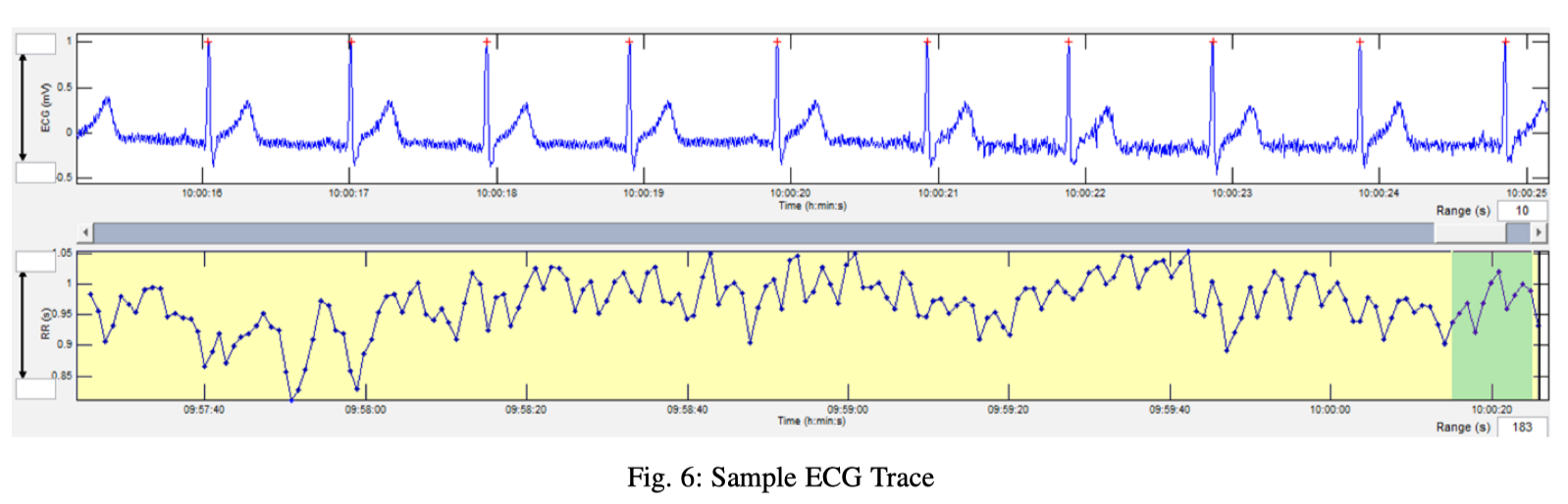
Figure 6 shows the sample ECG trace from subject one and RR intervals were calculated using Kubios HRV software and the RR series was produced by interpolation. This RR time series was used to calculate heart rate (HR) and HRV using the same software.
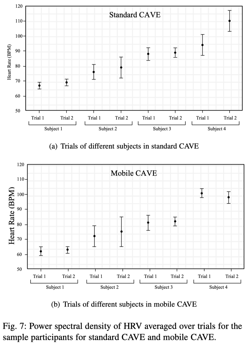
The average HR (with the standard deviation) for two independent trials for two CAVE configurations for four different subjects are shown in Figure 7. This clearly depicts that the inter-subject and intra-subject variability of heart rate during different trials and in different CAVE configurations.
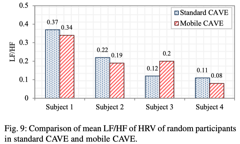
The RR time series was used to calculate the PSD using the AR method to identify the VLF, LF and HF frequency component of the HRV. Figure 8 shows the PSD averaged over trials for sample participants in case of mobile and standard CAVE. The summary of the mean PSD different participants are shown in Figure 9. The LF and HF power were expressed in absolute terms (ms 2 ) and in units normalized relative to total power (minus the VLF component). It was obvious from Figure 8 (a) and (b) that the HF power was comparable for mobile and standard CAVE however, the LF power varies according to the subject involvement in the experiment. This result also complies with the subjects survey result shown in Table 1.
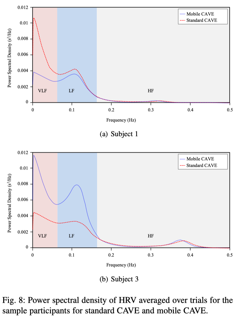
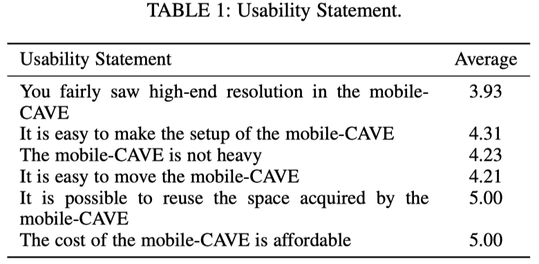
Figure 9 shows that LF/HF is higher for most of the subjects but the difference in LF and HF power is not very high; however, for subject three LF power is much higher than HF power. This is also reflected in Figure 8 (b), which shows that HF power is same for both the CAVE configurations but the LF power is significantly different.
4.3 Power Consumption
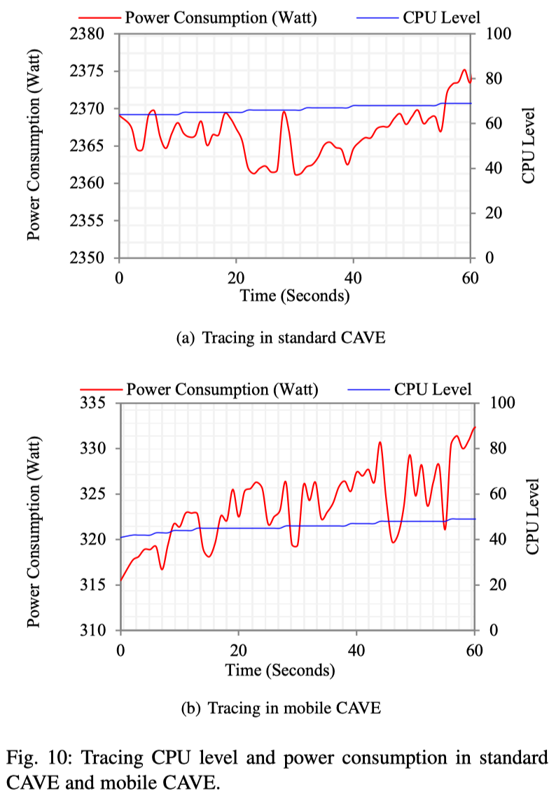
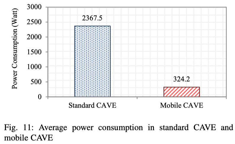
We compared the power consumption of installed devices in the standard CAVE and the mobile-CAVE. We did not consider the power consumption of tracking cameras. This is because our study considers the infrastructure of the CAVE. We assumed that tracking cameras independently submit tracking data to the main device. The standard CAVE was equipped with four Christie DS+6K-Mirage projectors by Christie Digital 3 and four DELL Precision T7600 computers provided by DELL 4 . In our mobileCAVE, we used four Sony MP-CL1A mobile laser projectors 5 and four ASUS ROG GL702V VR enabled laptops supplied with NVIDIA GTX 1070 6 and 24GB RAM. During the operation of the simulation, we recorded the CPU level of the main machine and the power consumption of each CAVE system. To measure the power consumption, we employed a custom power meter which takes power from the main power socket and provide power to the CAVE system. Figure 10 shows the CPU level and the power consumption in watt (W) for the two CAVE systems for one minute operation. Figure 11 shows the average power consumption of the two CAVE systems. In fact, our proposed mobile-CAVE achieved the optimal power-saving level with acceptable rendered frame-rate synchronization. We noted that with the increase of CPU-processing level, the power-consumption is also increased. Consequently, the power consumption of the proposed mobileCAVE is approximately 324.2±4.18W while the power consumption of the standard CAVE is approximately 2367.5 ± 4.43W.
4.4 Usability and Mobility Analysis
We asked participants to fill a survey after they used the developed simulation in the standard CAVE and the mobile-CAVE. We put an assumption that the usage of the standard CAVE and the mobileCAVE must provide the same level of user interest. Later on, we asked participants to move the mobile-CAVE and place it in different place. In terms of picture clarity and brightness, participants preferred the standard CAVE because it produces clearer picture with distinctly saturated colors. Our mobile-CAVE uses mobile projectors, and their colors becomes soft especially if there is background lighting in the room. In terms of mobility, participants failed to move the standard CAVE. In fact, they preferred the mobile-CAVE as they were able to move the equipment easily without expertise or training. This is because the mobile-CAVE is equipped with light-weighted materials. Moreover, users preferred in general to use the mobile-CAVE because it solves several limitations, such as space allocation and mobility. Table 1 shows survey results of participants.
4.5 Cost Analysis
We studied the price of different CAVE systems available in the market. In fact, the price is affected by the provided features of each CAVE system. The average price of the available CAVE systems is approximately 450K ± 355K USD. Thus, existing CAVE systems use high-end machines and large projectors. However, our proposed mobile-CAVE system does not cost more than 20K USD. This is because the system is supplied with mobile projectors and laptop devices. In addition, the integrated walls are composed from vellum bristol papers and does not include expensive materials.
4.6 Discussion
In our study, we discussed the efficiency of our proposed mobileCAVE in comparison with the standard CAVE. Based on the filled surveys and the obtained assessments results, it was clearly revealed that the effective involvement in the simulation game in the CAVE environment could be subjective. However, the standard CAVE produces slightly higher involvement in a cognitive task but the result was comparable in our proposed configuration. Most significant advantage of the mobile-CAVE is its portability and mobility feature, which was also agreed by all the participants. This is because it can be easily moved and benefit from its allocated space. Thus, it enables the user to get the benefit of CAVE technology in schools, hospitals and market places without practically paying thousands of dollars to setup in those premises. Moreover, the power consumption of the mobile-CAVE is remarkably less than the standard CAVE. This is because laptop devices and mobile projectors consume much less power than normal PCs and normal projectors. Additionally, the employed mobile projectors in the current prototype can project, using their batteries, continuously for two hours if fully charged. It can be concluded that our proposed design of mobile-CAVE system could replace standard CAVE system.
5 CONCLUSION
The CAVE has assured to be an efficient and persuasive VR model that expands the capability and increases the VR experience. It fulfills the purpose of presenting large angle view, making fullcolor high resolution images, and permitting multi-person to work. The proposed mobile-CAVE solves some shortcomings of the standard CAVE technology. These shortcomings include, cost, mobility, re-usage of allocated space, and power consumption. The experimental analysis results showed the usage of the standard CAVE and our proposed one are nearly matching.
6 FUTURE WORK
Future research efforts will consider the employment of low power consuming cameras to track the movement of the user. We have interest in presenting stereoscopic images through 3D mobile projection. In addition, the design and implementation of high-speed wireless mobile-to-mobile communication is planned.
REFERENCES
[1] C. Cruz-Neira, D. J. Sandin, and T. A. DeFanti, “Surround-screen projection-based virtual reality: the design and implementation of the cave,” in Proceedings of the 20th annual conference on Computer graphics and interactive techniques. ACM, 1993, pp. 135–142.
[2] D. Pape, J. Anstey, M. Bogucki, G. Dawe, T. DeFanti, A. Johnson,D. Sandin et al., “The immersadesk3-experiences with a flat panel display for virtual reality,” in the proceedings of the Third International Immersive Projection Technology Workshop, Stuttgart, Germany, 1999, pp. 107–112.
[3] T. Wischgoll, “Display systems for visualization and simulation in virtual environments,” Electronic Imaging, vol. 2017, no. 1, pp. 78–88, 2017.
[4] J. M. Hegie, A. S. Kimmel, K. H. Parian, S. M. Dascalu, and F. C. Harris Jr, “Wield-cave: Wireless ergonomic lightweight device for use in the cave,” Journal of Computational Methods in Sciences and Engineering, vol. 10, no. s2, pp. 177–186, 2010.
[5] J. Martins, R. Gonc¸alves, F. Branco, L. Barbosa, M. Melo, and M. Bessa, “A multisensory virtual experience model for thematic tourism: A port wine tourism application proposal,” Journal of Destination Marketing & Management, 2017.
[6] Y. He, Z. Zhang, X. Nan, N. Zhang, F. Guo, E. Rosales, and L. Guan, “vconnect: perceive and interact with real world from cave,” Multimedia Tools and Applications, vol. 76, no. 1, pp. 1479–1508, 2017.
[7] C. Cruz-Neira, D. J. Sandin, T. A. DeFanti, R. V. Kenyon, and J. C.Hart, “The cave: audio visual experience automatic virtual environment,” Communications of the ACM, vol. 35, no. 6, pp. 64–73, 1992.
[8] M. Mine et al., “Virtual environment interaction techniques,” UNC Chapel Hill computer science technical report TR95-018, pp. 507 248–2, 1995.
[9] R. Wolff, C. Preusche, and A. Gerndt, “A modular architecture for an interactive real-time simulation and training environment for satellite onorbit servicing,” Journal of Simulation, vol. 8, no. 1, pp. 50–63, 2014.
[10] M. C. Cabral, C. H. Morimoto, and M. K. Zuffo, “On the usability of gesture interfaces in virtual reality environments,” in Proceedings of the 2005 Latin American conference on Human-computer interaction. ACM, 2005, pp. 100–108.
[11] X. Nan, Z. Zhang, N. Zhang, F. Guo, Y. He, and L. Guan, “vdesign: a cave-based virtual design environment using hand interactions,” Journal on Multimodal User Interfaces, vol. 8, no. 4, pp. 367–379, 2014.
[12] T. Nguyen-Vo, B. E. Riecke, and W. Stuerzlinger, “Moving in a box: Improving spatial orientation in virtual reality using simulated reference frames,” in 3D User Interfaces (3DUI), 2017 IEEE Symposium on. IEEE, 2017, pp. 207–208.
[13] S. Zhang, C. Demiralp, and D. H. Laidlaw, “Visualizing diffusion tensor mr images using streamtubes and streamsurfaces,” IEEE Transactions on Visualization and Computer Graphics, vol. 9, no. 4, pp. 454–462, 2003.
[14] L. E. Potter, L. Carter, and A. Coghlan, “Virtual reality and nature based tourism: an opportunity for operators and visitors,” in Proceedings of the 28th Australian Conference on Computer-Human Interaction. ACM, 2016, pp. 652–654.
[15] A. Rovira and M. Slater, “Reinforcement learning as a tool to make people move to a specific location in immersive virtual reality,” International Journal of Human-Computer Studies, vol. 98, pp. 89–94, 2017.
[16] A. W. Dhowian, “Laboratory simulation of field preloading on jizan sabkha soil,” Journal of King Saud University-Engineering Sciences, vol. 29, no. 1, pp. 12–21, 2017.
[17] D. Yuen, M. Santoso, S. Cartwright, and C. Jacob, “Eukaryo: An ar and vr application for cell biology.” International Journal of Virtual Reality, vol. 16, no. 1, 2016.
[18] A. Bierbaum, C. Just, P. Hartling, K. Meinert, A. Baker, and C. CruzNeira, “Vr juggler: A virtual platform for virtual reality application development,” in Virtual Reality, 2001. Proceedings. IEEE. IEEE, 2001, pp. 89–96.
[19] FreeVR. Virtual reality integration library. [Online]. Available:http://www.freevr.org/
[20] D. M¨uller, F. W. Bruns, H.-H. Erbe, B. Robben, and Y.-H. Yoo, “Mixed reality learning spaces for collaborative experimentation: A challenge for engineering education and training,” International Journal of Online Engineering (iJOE), vol. 3, no. 4, pp. 15–19, 2007.
[21] D. Zhou, J. Chen, C. Lv, and Q. Cao, “A method for integrating ergonomics analysis into maintainability design in a virtual environment,” International Journal of Industrial Ergonomics, vol. 54, pp. 154–163, 2016.
[22] M. A. Muhanna, “Virtual reality and the cave: Taxonomy, interaction challenges and research directions,” Journal of King Saud UniversityComputer and Information Sciences, vol. 27, no. 3, pp. 344–361, 2015.
[23] D. Kulich, S. Gaggar, V. Lowry, and R. Stepien, Acrylonitrile–butadienestyrene polymers. Wiley Online Library, 2002.
[24] M. Suckle, “Hdmi cable head,” May 22 2007, uS Patent D543,156.
[25] M. D. Hanson, “The client/server architecture,” Server Management, p. 3, 2000.
[26] T. Van Cleave and L. Van Cleave, “Projector for track alignment reference systems,” Jun. 29 2016, uS Patent App. 15/197,036.
[27] K. D. Rueb, “Laser projection system using variable part alignment,” Jan. 26 2016, uS Patent 9,245,062.
[28] R. H. Creighton, Unity 3D game development by example: A seat-ofyour-pants manual for building fun, groovy little games quickly. Packt Publishing Ltd, 2010.
[29] M. P. Tarvainen, J.-P. Niskanen, J. A. Lipponen, P. O. Ranta-Aho, and P. A. Karjalainen, “Kubios hrv–heart rate variability analysis software,” Computer methods and programs in biomedicine, vol. 113, no. 1, pp. 210–220, 2014.
[30] N. Ahmed and K. R. Rao, “Fast fourier transform,” in Orthogonal Transforms for Digital Signal Processing. Springer, 1975, pp. 54–84.
[31] H. Baali, R. Akmeliawati, M.-J. E. Salami, A. Khorshidtalab, and E. Lim, “Ecg parametric modeling based on signal dependent orthogonal transform,” IEEE Signal Processing Letters, vol. 21, no. 10, pp. 12931297, 2014.

涉及工具